In an industry where automation becomes a constant request a presetter with that provided an autofocus capability becomes a necessity.
In this article we explain how to select a presetter with autofocus because such a capability is a very useful solution for any modern mechanical workshop.
There are two main reasons for choosing a pre-registration and measurement system of tools which adopts both a motorized C axis and software capable of automatically recognizing and measuring the cutting edges. The the need for a solution that minimizes human error and also one that provides the measurement of tools which feature multiple cutting edges that would be very complex if done manually.
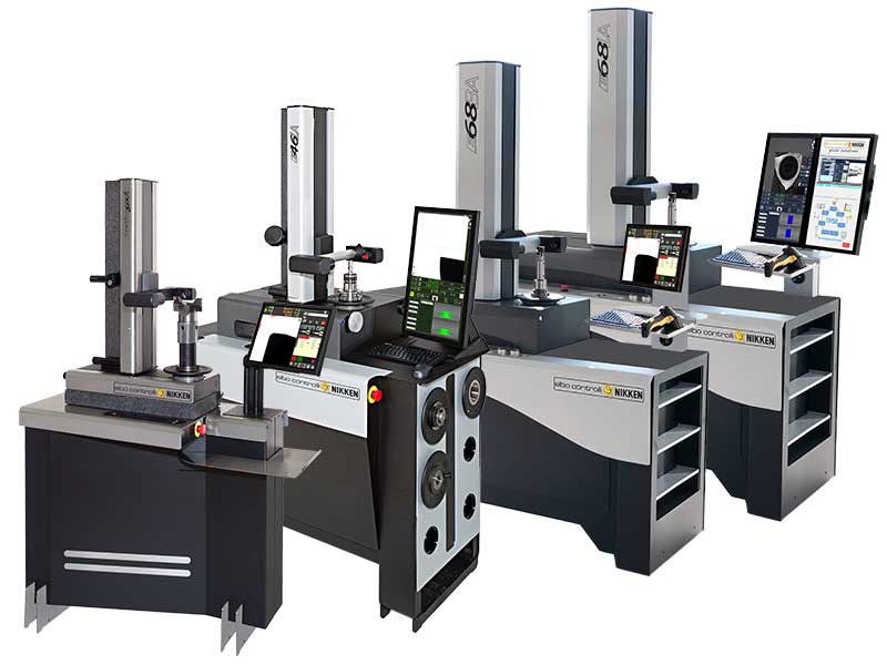
Our ‘A’ solution, available for the Hathor Six, E46L, E68B and E68L models, allows users to reduce the possibility that the presetter operator suffers error in the measurement of the tools, thanks to the systems developed by Elbo Controlli NIKKEN.
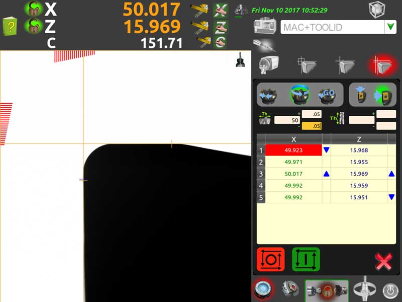
Once the tool is clamped the operator simply has to choose what type of measurement he wants to carry out (single cutting edge or multi-cutting edge) and what to measure (X, Z or both axes) then start the measuring cycle. There is no requirement to enter the number of cutting edges to be measured or any theoretical values, unless a complete report is required with tolerancing, the software will start the cycle autonomously and will end it once the 360 ° rotation has been performed.
Elbo Controlli NIKKEN adopts a system that adapts and controls the peripheral speed of rotation of the tool according to the maximum diameter to be measured. The constant peripheral speed avoids the introduction of errors whether you are measuring a tool with a diameter of 2 mm or one of 200 mm.
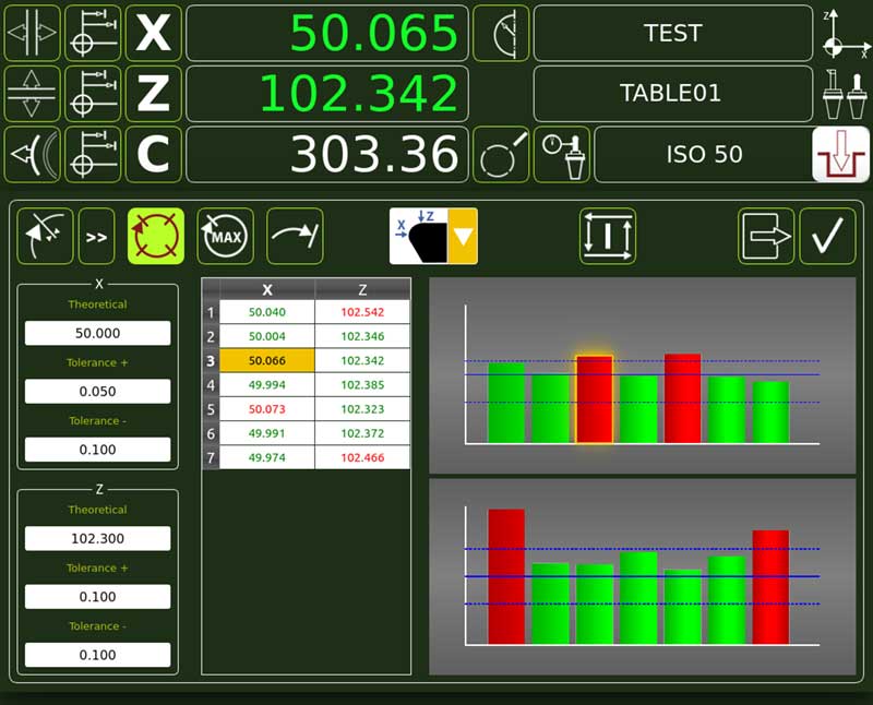
If the theoretical values and tolerances for the individual cutting edges have been entered the presetter will immediately display the measurement table which highlights all measurements and those that are out of tolerance. It is then possible, by choosing the desired cutting edge from the table, to reposition the spindle automatically to that edge to allow it to be adjusted or even the insert/edge in question be replaced.
Once the measurement cycle is finished, the data obtained is available to be printed on a label, saved in the tool table or stored and made available for the TID tool identification system. The latter two methods of tool data output allow the concept of process automation to be taken to the next level and also eliminate the possibility that the operator makes mistakes when entering these values in the machine.